Monday, 19 December 2011

Monday 19/12/11

Hi
Well the bush saga so far!
Fantastic, well that's maybe a bit OTT; but I am very pleased with the Teflon mockups. I have test fitted them in every position and they slide in with perfection, so they are on there way to Flo-flex on next day delivery. Hopefully they will give me a realistic price on the mould and not try to rip me.
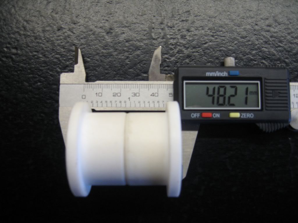
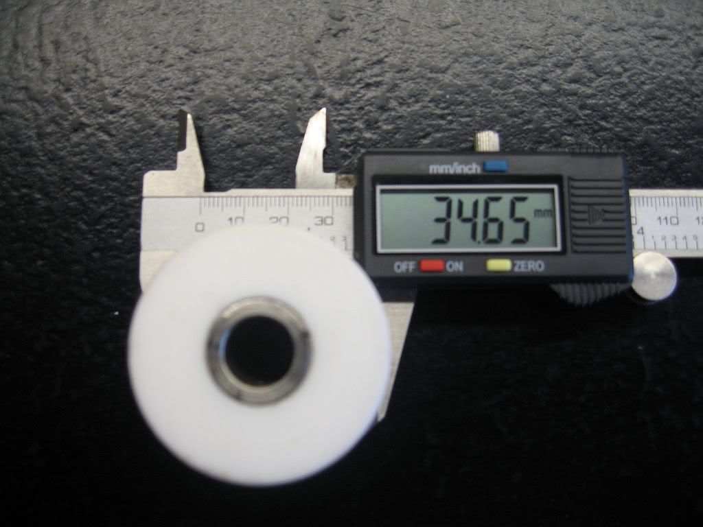
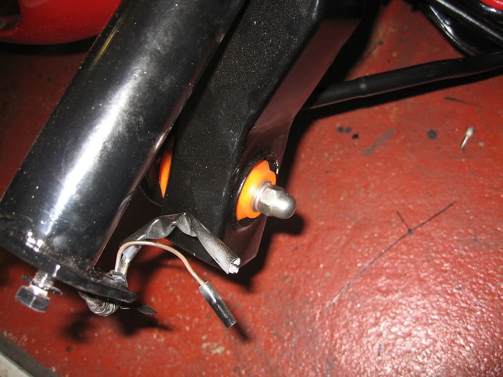
This is the 12mm center I mentioned in my last blog, I have not asked but they may be able to make the centers to 7/16" for the lower arms as fitted. I had to grind the nuts off mine as there was no way I could get them to turn so 12mm is ideal.
If anyone reading has been looking for a set of rear poly bushes for their car then please give Flo-flex a ring and voice your interest for when my set have been made and fitted, it may gee them along a bit. 0044 (0)1745360070

I have managed to carry on with a few other bits despite my wife wanting a bit of attention.
First was that last wing, I got the wire wheel on it and hiding under the old underseal was a lovely hole.
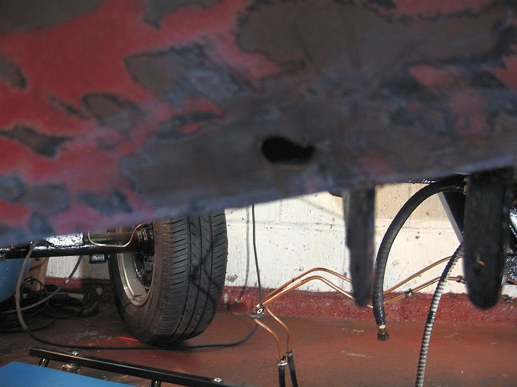
Hole in wing
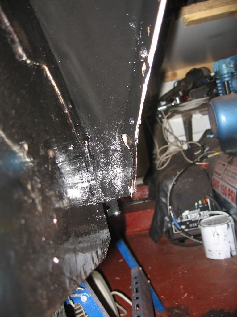
I have sprayed the inside of the holed box section with rust converter before welding a patch on and given it a good coat of chassis black, once covered with undercoat it will be invisible.
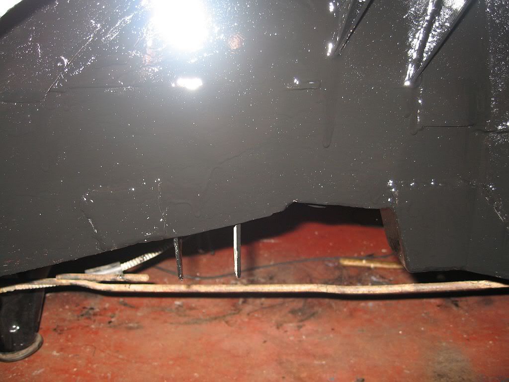
welded patch Ok I'm not the best mig welder
It was the same story in the rear corner of the inner wing as it was with the other side in that there was a hole cut into the steel section when it was formed, I have filled the holes in on both sides using gutter sealant which is designed to stop water ingress so no more problems from that area and I would advise all to check, a very vulnerable spot.
So that is the the whole of the back section painted upto the gearbox.
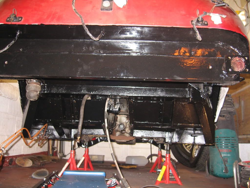
rear underside painted
 Next is the gearbox, I remembered reading the latest thread in the club tech forum about gearbox removal and checked it out again. Lots of info in here, mainly the answer to my question of which type it is, well it's a Ford type 9 box and lots of bits available for this box. I have been on Ebay and searched out a set of new oil seals and found a set from the same business that supplied the diff oil seals. You get 3 seals in a pack, which is just as well because the rear is leaking, the speedo is leaking and there is oil around the front of the box which could be either from the engine or the front seal, don't know yet. Unlike the removal of the diff seal I have splashed out a fiver and bought an oil seal removal tool, so taking these out should be a doddle.
I started with the starter motor; this is quite easy although the top nut is rather difficult to get at, luckily it turned off quite easily.
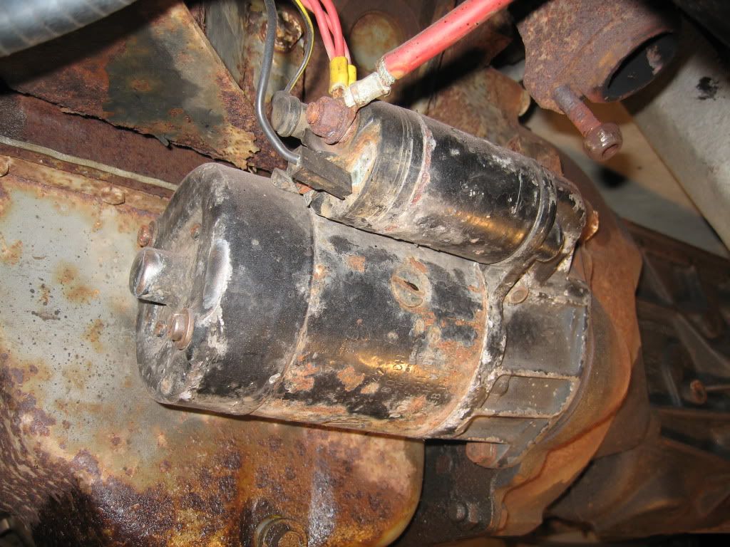
Starter & electrics
I don't know yet what servicing I can do on this but I have the big boy's book off classic car electrics of which I shall digest avidly.
I still have to drain the gearbox of its oil which I shall do once I find the drain plug, unfortunately my big nose was touching the bottom of the gearbox so I had to raise the car to the last hole on my stands. Very uncomfortable feeling being under a car sitting on a fully extended set of Aldi axle stands so I am off to Halfords tomorrow to buy some jackable heavy duty stands for Christmas and I may see New year (although not in this country).
There are 7 main items to remove before undoing the bell housing bolts; the starter motor (done):  the drive shaft (done): the reverse light (done): the speedo cable (done): the clutch cable (to do) gear stick (to do). the support bracket (to do)
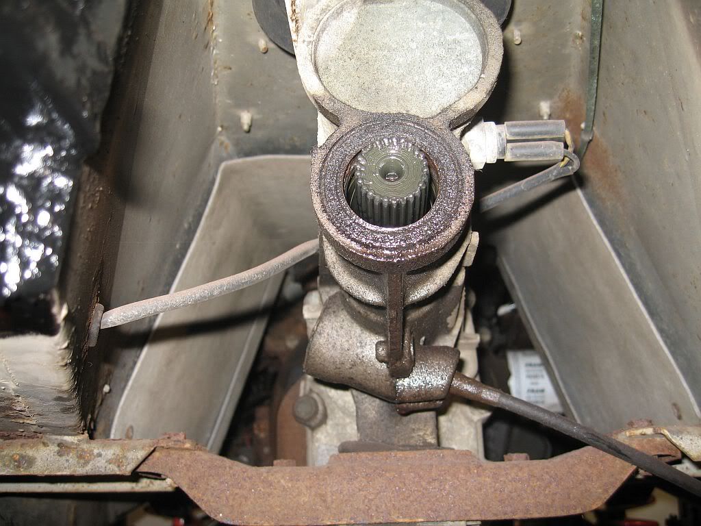
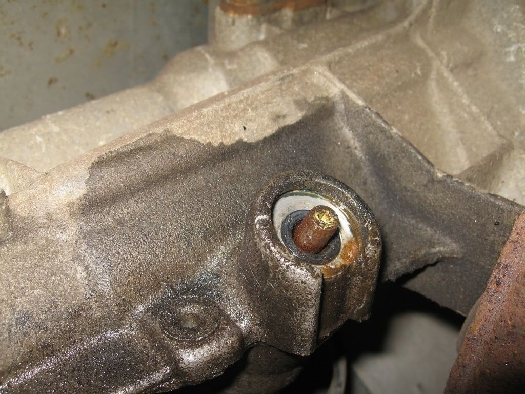
Reverse, speedo and hanger & leaky seal
 The drive shaft I have already removed, just paint mark the flange to the diff and remove the bolts then tap the flange if it doe's not free immediately. Drop down to clear from diff flange and pull out.
The reverse light has a twist connection that is easily undone and just pulls clear.
The speedo cable is a little more involved well it was for me as I did not have circlip pliers of the right size, mine are off the standard size whereas the circlip fitted has very small holes. So it was out with the dremmel and sanding attachment and ruined a good set of pliers to get them to fit. Still its out now
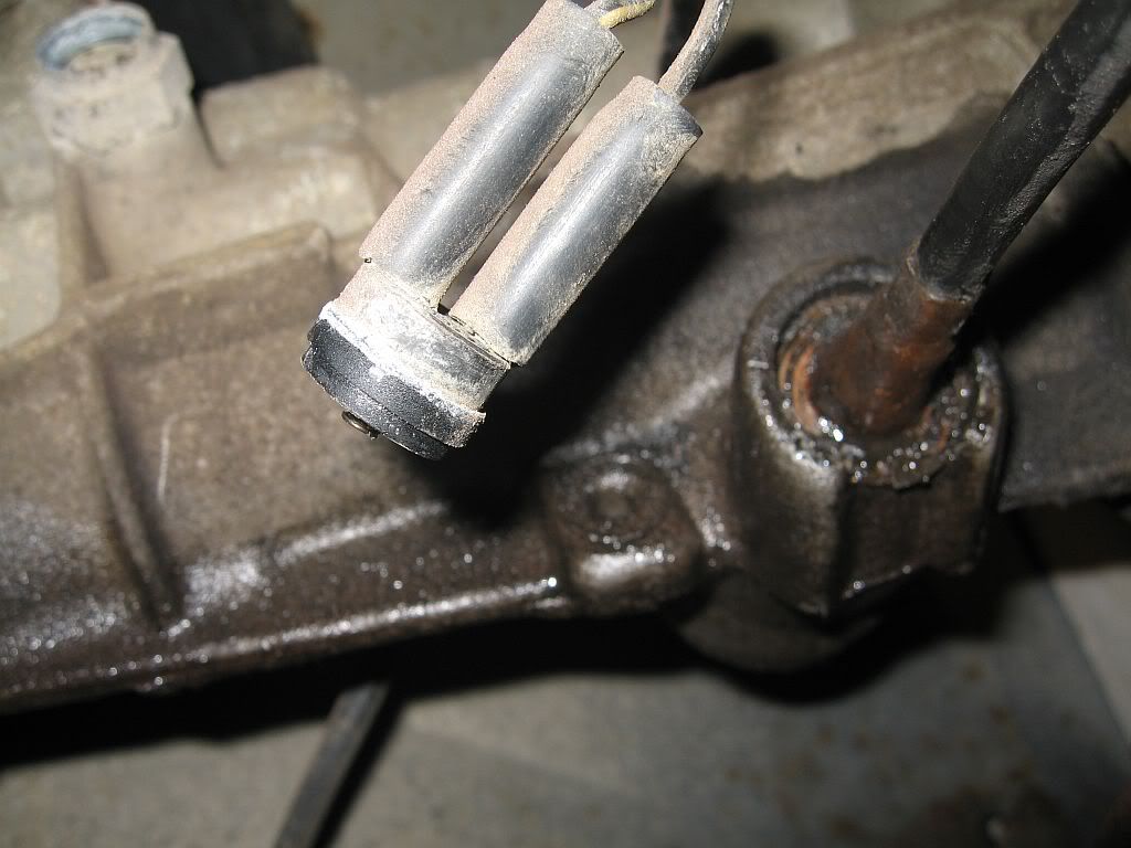
Reverse light removed, speedo leaking
Cable removed
You can see the leaking oil seal which will be replaced.
Well that was about all I have managed today and will carry on tomorrow If I can figure out how to remove the clutch cable, the gear stick and drain it of oil; which is off course all part of the fun.
Well thats all for now as a pint of Guinness has just been put in front of me.
see ya Paul

Friday, 16 December 2011

Friday 16/12/11

Hi
Well back home for Christmas leave so hope to get some work done while I can, not much done yesterday as I had a MRI scan arranged; noisy things but still managed to fall asleep inside the machine.
Today's main task was getting the rear axle finished so it was mostly brakes, yesterday about all I managed to get in was the brake pipes polished up with wire wool and refitted plus a bit of wire wheel cleaning.
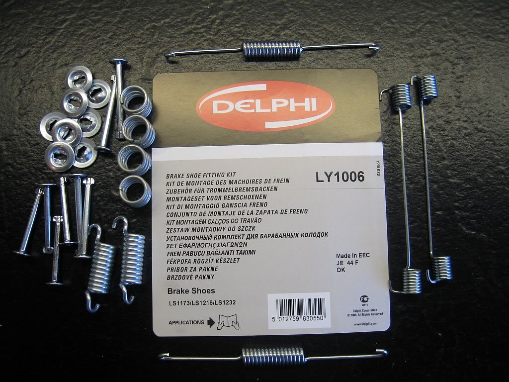
I have bought a new set of shoes and springs for the brakes, I was considering new pistons but after a turn on the wire wheel they came up like new, I think these where changed by the last owner and have no millage on them. The piston are from a 2.0lt Capri whereas the shoes and springs are from the 2.8 to get the front and rear braking balance correct, I hope I ordered the correct items as I discovered a problem with the adjuster springs. The problem I spotted is that there is a left and right hand spring fitted to the car but the spring pack contained 2 right hand springs, I suppose I could have fitted it ok but thought it safer to use the old one polished up.
Spring pack for 2.8 Capri
You can see in the picture the 2 short springs are the same but should be left and right, not a problem as the rest are identical to what came off.
Ford Capri 2.8 Spring set Ebay    £11 inc p+p

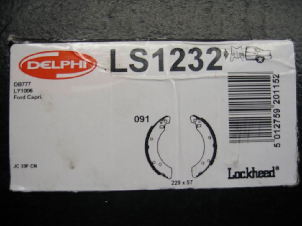
The brake shoes were also from Ebay, no problem this time as they matched and fit perfectly
Capri drum brake shoe number
As I mentioned in a previous blog I have never had any dealings with drum brakes in the past and was a bit wary of them, I even had my Haynes book of brakes out and studied the different types. After looking at some of the others these are defiantly the easiest.
It took quite a few attempts this morning to fit the *^"* things until I discovered what I think is the easiest way for one person, never realised I was so kack handed until I tried balancing springs and shoes. This is the way I found best so hopefully if anyone out there wants to save some money by fitting there own then here is my attempt.
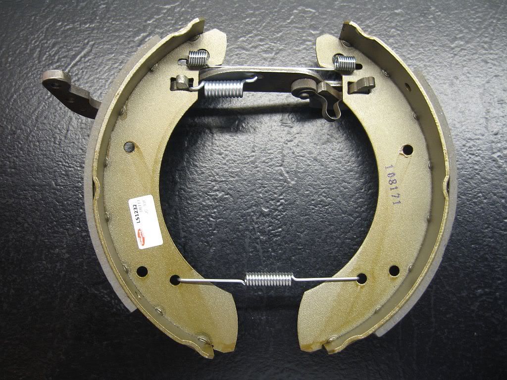
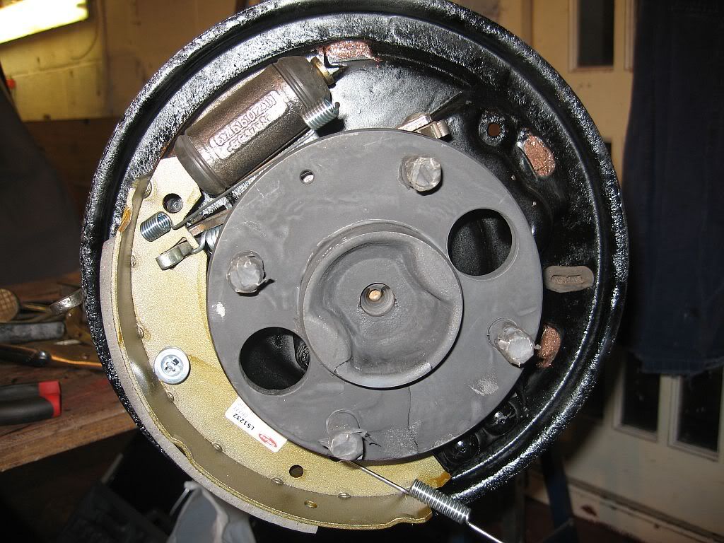
1, I found it easy to understand by laying the shoes and springs out on a table to see what goes where, of course I photographed everything before I removed them. It is also important to get the shoes the right way around, as you can see one side of the friction material is higher than the other
Setup to understand
   
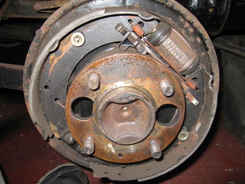
Original setup
This is the photo I had to work from, this was taken of the left hand side as you can see from the suspension spring. The friction material is lower down on the shoe facing the direction of travel. Typically I started fitting and photographing on the right hand side of the axle so the photo's show thing back to front with the direction of travel to the right of the fitting photograph's.
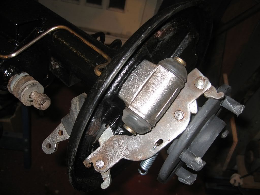
2, The first job is to lubricate the sliding plates on the back casing, I just used copper slip although proper brake grease is available. Then slide the handbrake / auto adjuster arm with the adjuster spring in place through the hole and fit the rubber boot on at the back, if this is forgotten it is rather difficult to fit after the spring tension is on the arm. (I found out on one of my attempts)
Handbrake lever/adjuster in place
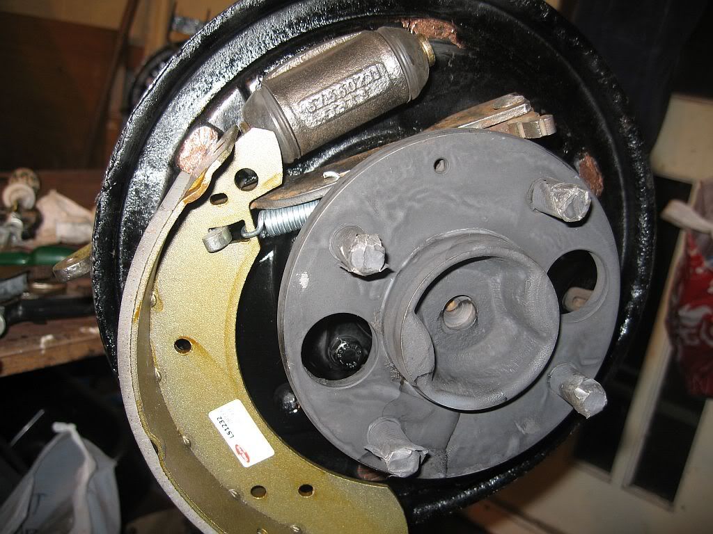
3, Fitting the left hand shoe, hold the adjuster and feed handbrake arm through the hole and attach the spring, a bit fiddly but it will fit easily enough.
4, The shoe now need to be held in place to fit the shoe retaining clip, first slide the bottom of the shoe into the anchor plate and the top of the shoe over the piston. Have a clamp ready to fit, then lock into position.
held by clamp
5, The shoe retaining clip can now be fitted, I did not have the correct tool available but found a pair of pliers worked just as well. Insert the pin from the back and fit the spring, hold retaining clip at the end of the pliers, line up the cutout, push on and turn.

4,  Now fit the upper and lower return springs

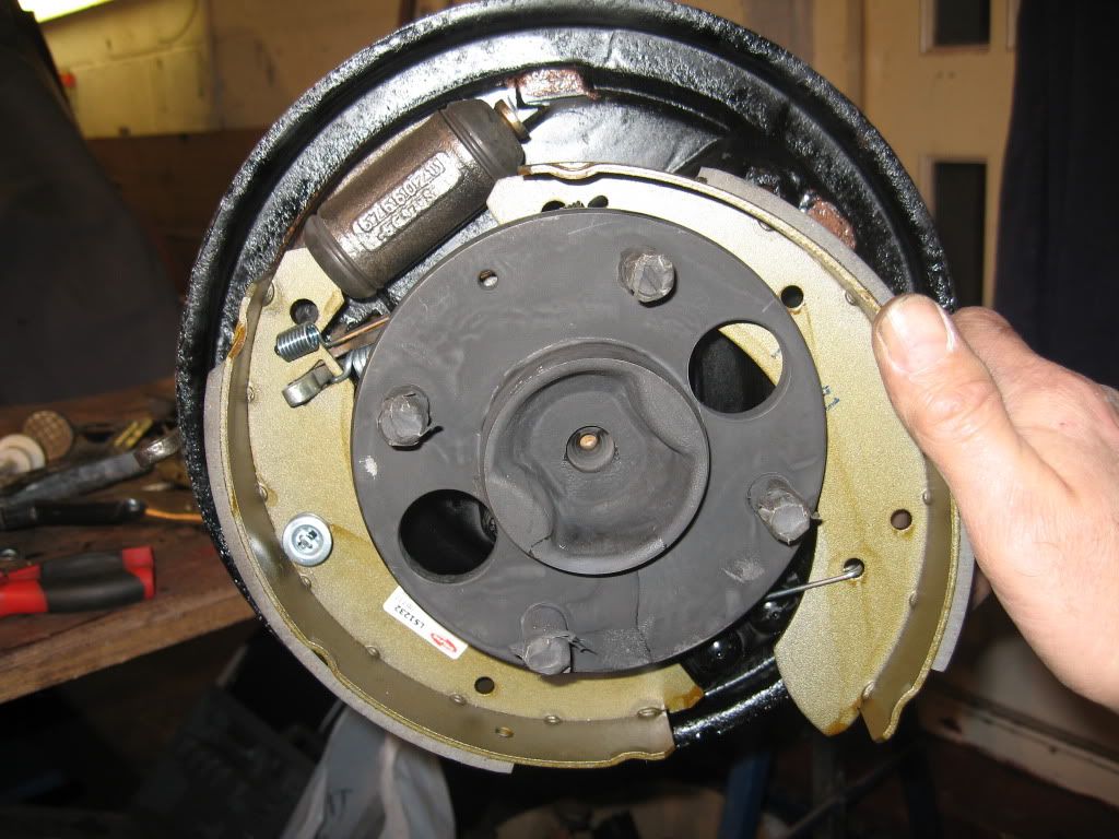
5, Take the other shoe and fit the auto adjuster arm thru its hole, then clip the upper and lower springs in place, doing it like this means that there is still a bit of play in the springs so no effort required trying to stretch them.
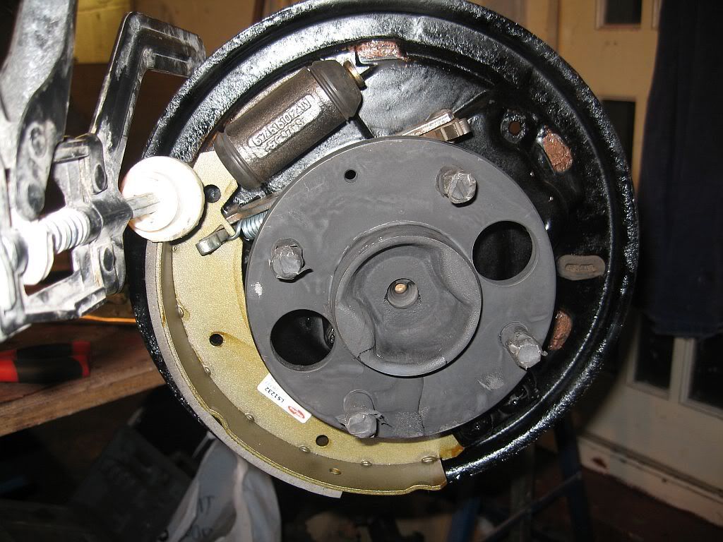
Other shoe attached to springs
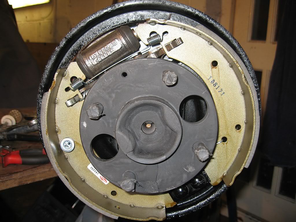
6, With the springs attached the bottom of the shoe can be pulled until it slips into the anchor point, now with a bit of force pull the top of the shoe until it slips over the piston then push onto the backing plate.
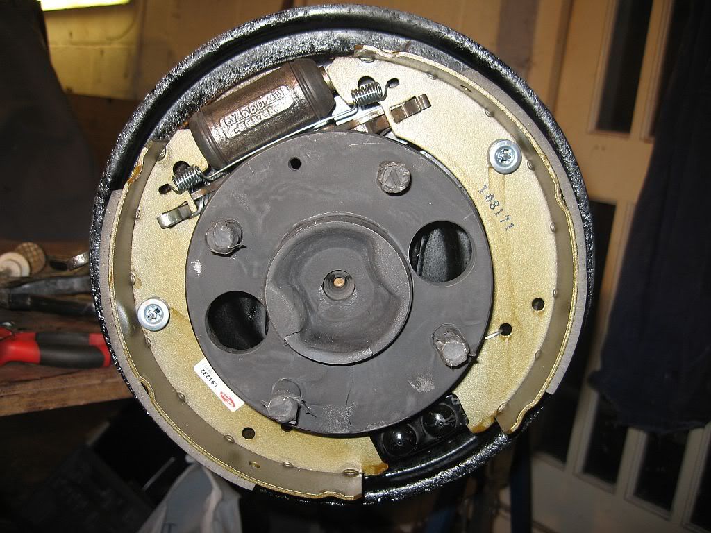
Shoe in place
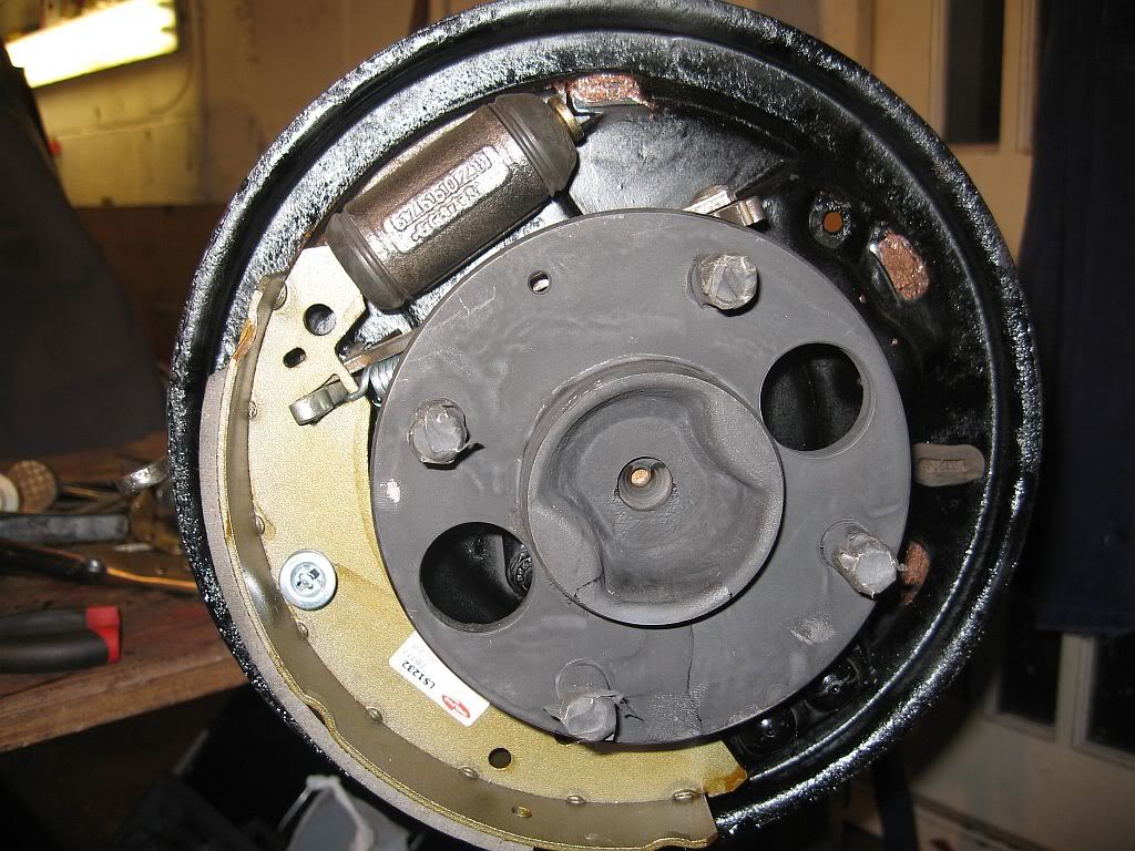
7, Now just a simple matter of fitting the other shoe retaining clip and all done. With all of the pulling the self adjuster will have pulled to its full extension, you just need to tap the edge of the serrated cam with a plastic hammer and it will drop back to its least position. It will then self adjust to the correct position when the drum is fitted.
 As with all published how too's, I cannot be held responsible for nipped fingers, dirty hands or any swearing, and of course your brakes not working after.
Once done I fitted the wheels and got the axle out of the way to make room, I still need to blast and paint the drums but that's for another day.
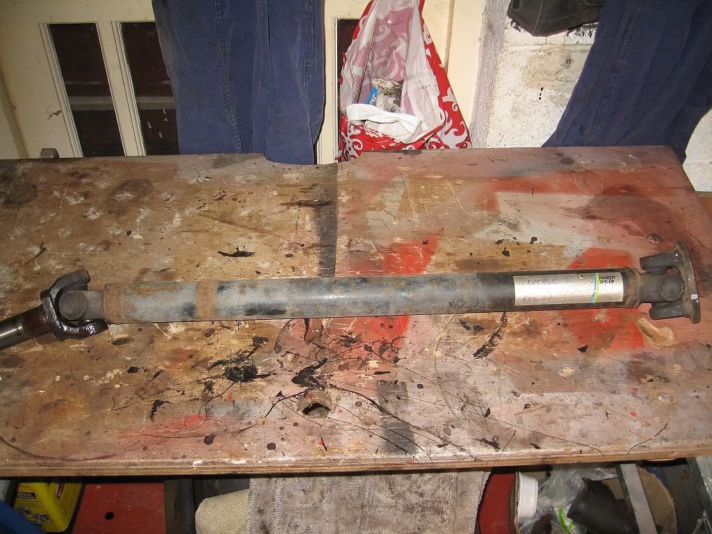
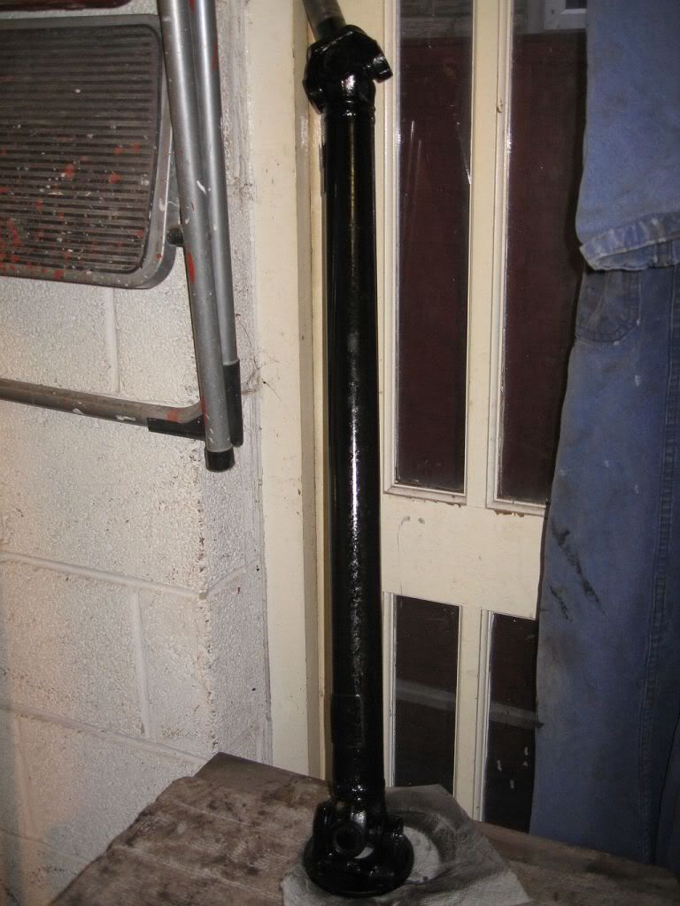
Next was the prop shaft, this just needed to be slid out of the drive. It appears to be in great condition just a bit of oily dirt around the gearbox end which appears to be from the oil seal on the gearbox leaking, as if I was surprised, I will have to ask Terry B what type of gearbox it is and order a seal. Once the shaft was cleaned and wire brushed a spray painting and good as new.
Before
 
After
Next was to get the exhaust out of the way, I have been soaking the bolts every time home so the pipes came off the manifold easily enough and the box just got knocked off. This has now given a lot more room underneath so it was out with a bucket of cleaner and I carried on with the underside. I have scrubbed up to the gearbox and scraped any rust and applied rust cure then out with the chassis black, just the right wing area to complete then all done till the engine / gearbox comes out.
That was that for the day.

Bush's!!! nothing but problems, you would think that after all these years it would be easy to get a set, well it is for the front but the rear is a different matter all together. The void bushes no problem, I have been in contact with Floflex a number times and they can supply the poly version of the void from either the Capri or the Cortina as Ford used the same bushes. It is the bobbins fitted to the Panhard and the upper and lower trailing arms that are causing problems, I have been reliably informed that these are possibly  from a Vauxhall Viva or suchlike. Terry B had an offer on through the club where Deflex supplied a close match and Terry modified these to suit, 50 sets were ordered and if Terry modified these then I bet they fit just fine.
The quandary I had was;
A, to modify a set like Terry B has done.
B, (of which was my favorite) was to say sod it and re-fit the originals, which would be a bit difficult for the 2 bobbins I removed for Floflex as they deformed a little and would be difficult to refit. or
C, Have a model of a correct size bush turned on a lathe then send of to Floflex for the correct mold to be made so as I and everyone in the future can just call Floflex and say I would like a rear poly bush set please.
So the decision was da da!
C, was the winner (at one point it was defiantly B but I won't be beaten on this) yesterday I dropped off the Panhard rod and a piece of Teflon rod with a Floflex stainless 12mm drilled center to an Engineering firm I have used in the past, I got a call today that it is ready to be picked up. Unfortunately I could not get there today so tomorrow I shall see what the guy has come up with, hopefully it will be spot on. There is only one small problem I foresee, not a problem for me but for some others; is that there is two different bolts sizes used, the upper arms and the Panhard are 1/2" BSF and the lower arms are 7/16" BSF. Where is the problem I here you say, well everything is metric these days so Floflex centre tubes will be in metric 12mm or 10mm, 12mm fits 1/2" perfectly whereas 10mm  is much less than 7/16" and would have to much play through the bolt on sections. So my remedy is to have both the upper, lower arms and Panhard at 12mm, this is where a few people may have problems in that you will have to either file or drill the holes out to fit the 12mm bolts. Its only a little but some people are not that way inclined.
Anyway I will find out tomorrow, only £20 for the mock up and Floflex will let me know how much for the making of the mold by the amount of material used, so if they charge me for the mold I hope I get commission for each set they sell other than mine. I shall post a picture of the model tomorrow.
Well that's all for now
see ya Paul

Tuesday, 29 November 2011

Tuesday 29/11/11

Hi
Well last day before I go back to work, (seem to say that a lot). Not as much to report this time home as most of it has been cleaning and painting.
With the axle and fuel tank out of the way I managed to get at the rear underside, as I said before this was in really great shape with just a few places needing a bit of rust removal and rust cure applied. Then a scrub up with degreaser and a bucket of floor cleaner and ready for painting, I removed the fuel pipes which are all new to the engine by the last owner then rubbed up the paint to give it a key and gave it a good coat of chassis paint. I started on the wheel arches next but only managed one of these, getting of the old undercoat was a bit messy but a wire wheel on my grinder made light work of it.
Just a note for those that are going to work on there car this winter, have a look and a feel under rear lower section of the wing as I found a hole. It feels like it is a proper cut hole and not corrosion and is in one of the worse places to be as all of the wet gets thrown into that corner, so a real corrosion problem.
Just a few inches from the bottom
This is defiantly going to get filled before underseal is sprayed on.
Next effort went on the fuel tank, a bit of rust on the lower weld edges and signs of brazing on 2 of the edge corners but other than that it cleaned up rather nice. I removed the sender unit which also looks in good condition, I don't know if it works yet but will put a meter on it before I refit and see if I get any readings.
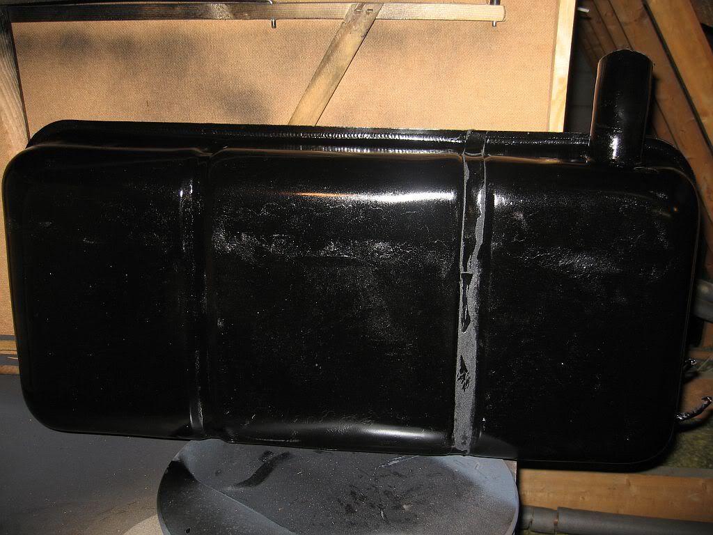
Fuel tank
After a good cleaning I gave it a couple of coats of primer then a couple of black and its ready to fit, need to wrap around some sound deadening strip to stop any road noise and rubbing first. Also had a look inside and its not to bad at all.
The axle came next, quite a bit of weight in this; you don't realise how much steel goes into one till you have to hump it around.
The brakes came first so lots of photo's for putting them back and stripped them off, I have been on eBay and ordered new springs and shoes, the shoes are here already but waiting for the spring set also found a hole in the handbrake lever dust boot which will either be repaired or replaced if I can find a supplier. Will put the number of these items on when I have fitted them.
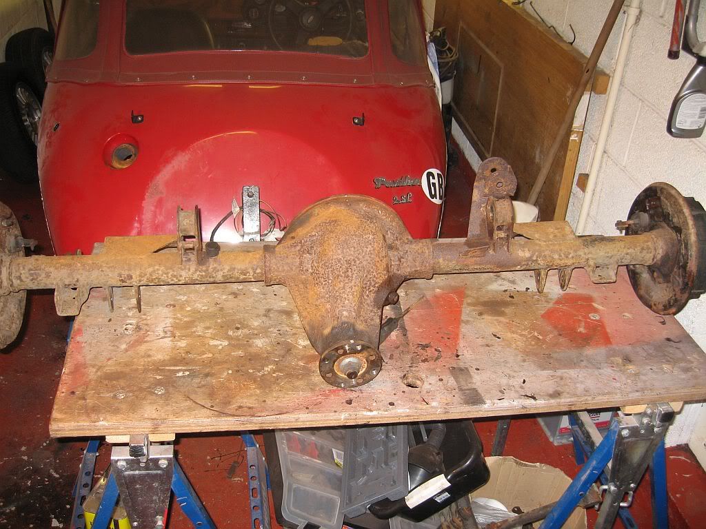
Next came cleaning the axle, this was done over a 2 day period first with sand blasting then the needle gun and then the rotary wire brush, not for the faint hearted but the results are defiantly worth it.
Axle before
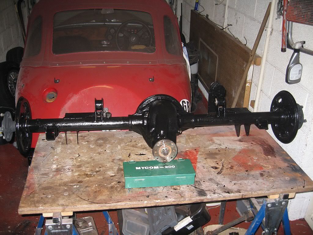
Axle after
I then attacked it with the hammerite and you can see the results. The brake areas I have sprayed with high temp paint which I shall also use on the brake drums when I get round to them, 2 days of hard lifting and cleaning but it looks like new.
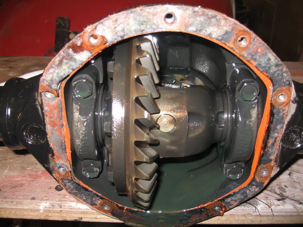
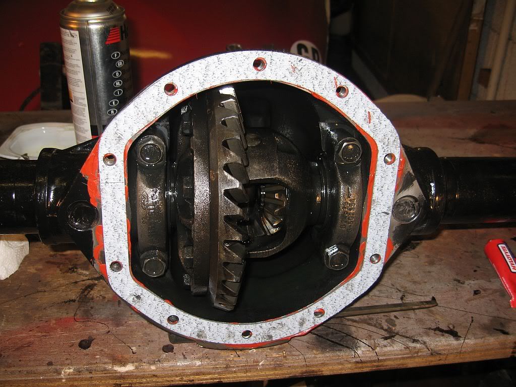
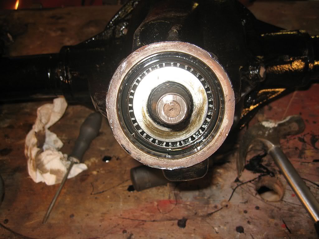
Now for the oil leaks, I suspected that the leak was from the gasket but did not want to fit the axle and find out it was from the pinion so I bought the oil seal and the gasket. The first to get a look at was the gasket, this was fixed on with a red sealant. I don't know if this is factory fit or has been replaced in the past but gave it a good cleaning.
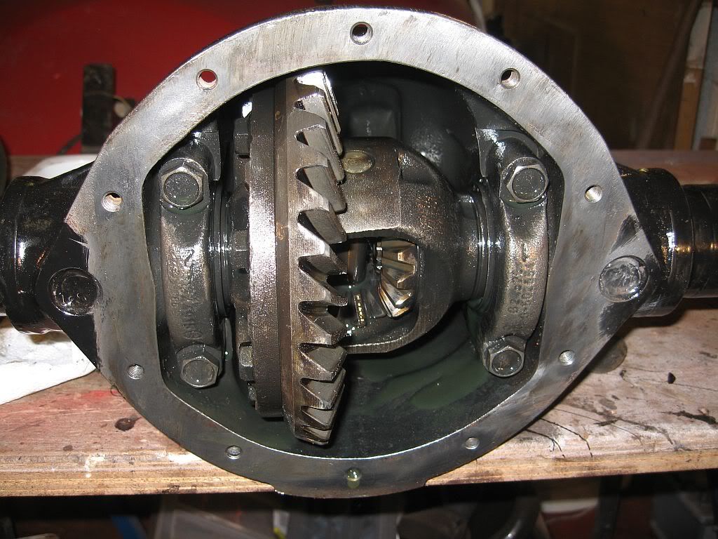
I also gave to inside a good staring at as I ain't got a clue what I was looking for, but all seems well; no wear on the teeth and no play or movement in the cogs or the shims so all good.
I bought some hylomar red for the refitting of the gasket and cover just to ensure a good seal, tightened it all back together and fingers crossed.
The next job was the pinion oil seal, I have never; and I imagine nearly everyone reading this will never have changed a one of these, so youtube got a good seeing to and it looked so easy; famous last words.
Well surprisingly enough it was just that easy.
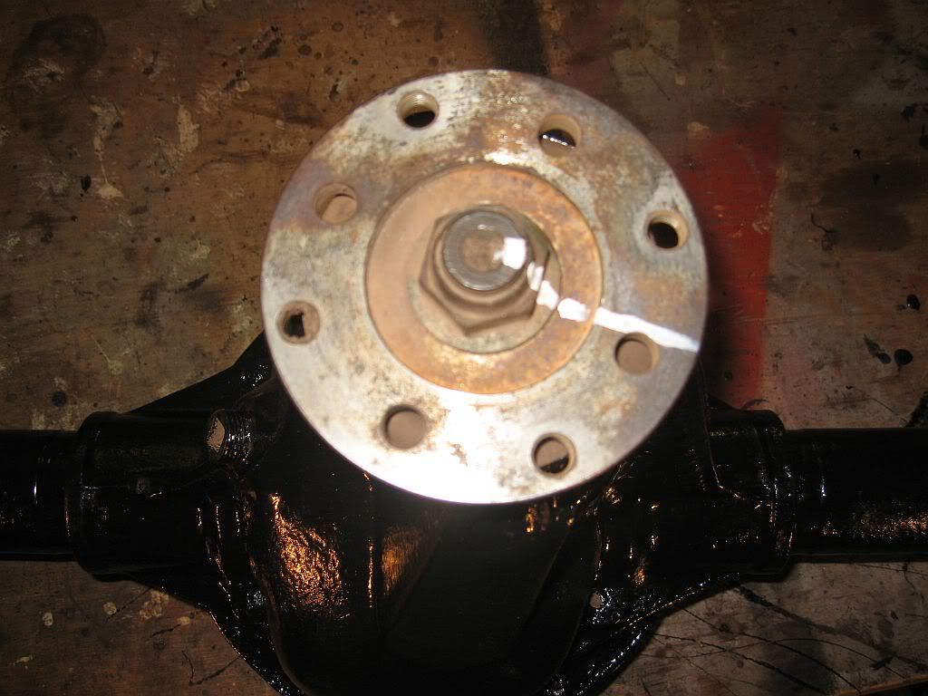
First job is to mark where the nut is positioned and to count the threads, this is because it has to go back exactly where it came from. It is factory torqued and there is a crush washer that needs to be pulled up to its original position.
Next, remove the nut, I had to use a impact gun to do this and a fully pressurised air bottle as it was on that tight. Once off, the flange just pulled off.
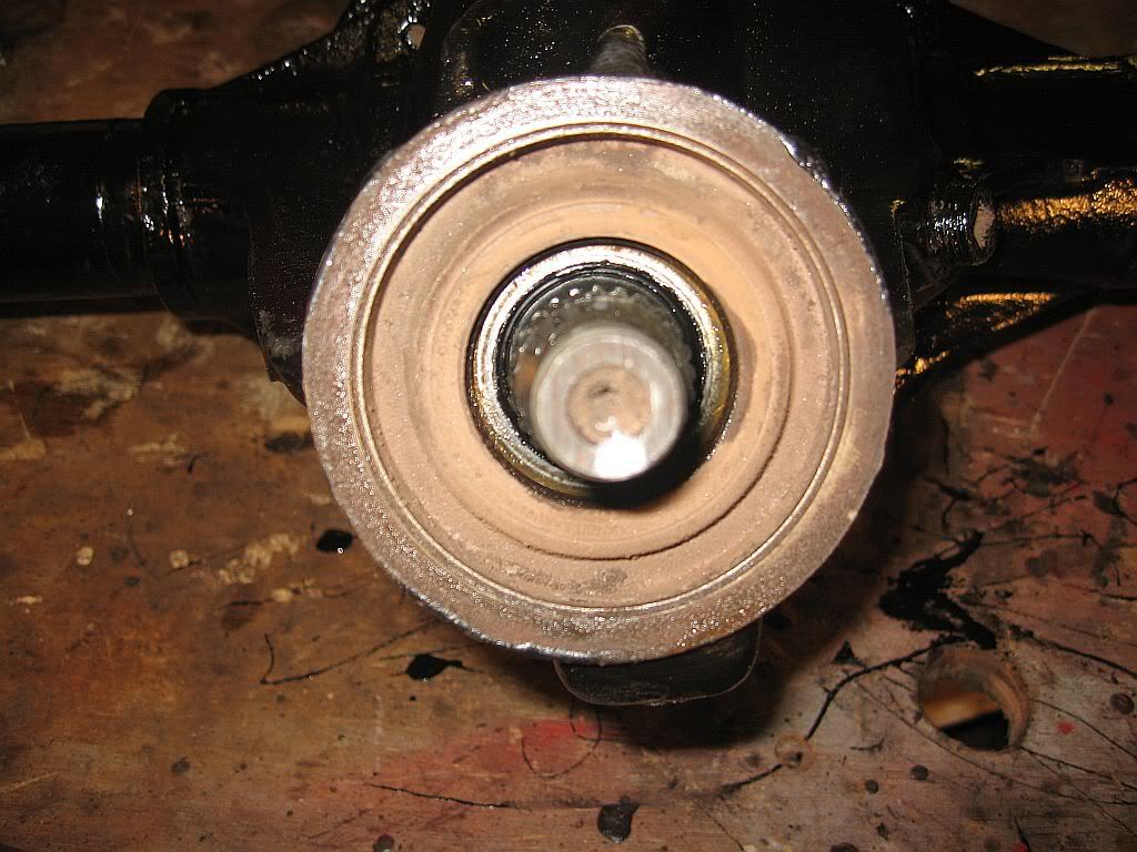
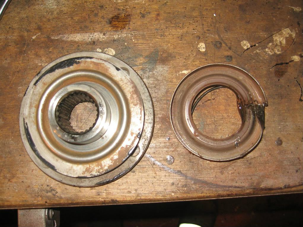
And there is the oil seal, it was covered in a lot of dust and crud which I imagine was from the sand blasting even though I tried to keep the stream away from the joint. On youtube it says to remove with special oil seal removal tool, ye right. I am afraid I had to revert to old fashioned methods of brute force and a huge amount of ignorance.
After a bit of persuasion out it came, of course I did try the new one up against it before whacking it. Here it is alongside the inside of the flange.
This is the inside of the pinion. Unfortunately I forgot to get a shot of the new oil seal in position, but it went in easy enough I just sprayed the inside with WD40 to give a little lube; fitted it in square and using a block of wood tapped all around until it was in position. I then replaced the flange on the paint marks and tightened back up until the paint marks all aligned and the correct count of threads were showing.
Of course I did all this on a bench, I would imagine it is a different ball game lying on you back under the car.
I had a run out and picked up a litre of 80 - 90 mineral oil and topped it up, I was expecting it to overflow from the fill hole but it took the whole litre straight of, I shall make enquiries as to the volume as it may require more to fill to correct level. I know a man who will know.
I have spoken to Cat at Flo-flex again today who has tracked down the 2 void bushes for the rear suspension but unfortunately has not had much luck on the rubber bobbin type bushes. She plans to keep on looking and is happy to make a mold if I can get a bush in good condition, unfortunately they need to be forced out and this squishes them a bit so no good for mold making. If anyone out they has a new bobbin bush that a mold can be made from then please let me know as once they have a set made then they will be available to any Kallista owner that wants to re-bush there car.
Well that's about all I got done this time home, hope for better progress next time if Christmas doesn't get in the way, I've asked Santa for Halfords vouchers.
See ya Paul

Thursday, 24 November 2011

Thursday 24/11/11

Hi
Back again for a weeks leave, I did a 3 week trip again as one of the lads went sick; lucky me. That's 3 weeks overtime since I bought the car and over 3/4's of my expected budget covered, 1 more extra week and I'll be looking at side exhausts.
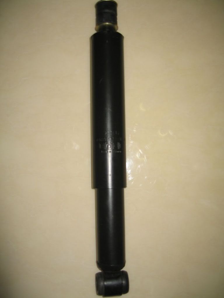
While away I have been trolling through ebay looking for some bargains and managed to pick up a few, the best being an original pair of Boge oil filled rear shocks for a Vauxhall Magnum. These are the shocks fitted to the Lima and will also fit the Kallista, unfortunately on trying them I found the bush holes larger than those fitted at 15mm where the Kallista has a 12mm bolt, still; not a problem as I just need to fit stainless steel inserts which I have already sorted, only cost £40 plus p&p. I was going to buy the Spax adjustable but having saved over £100 by buying originals I am well happy I shall also get a comfy ride instead of a sporty one.

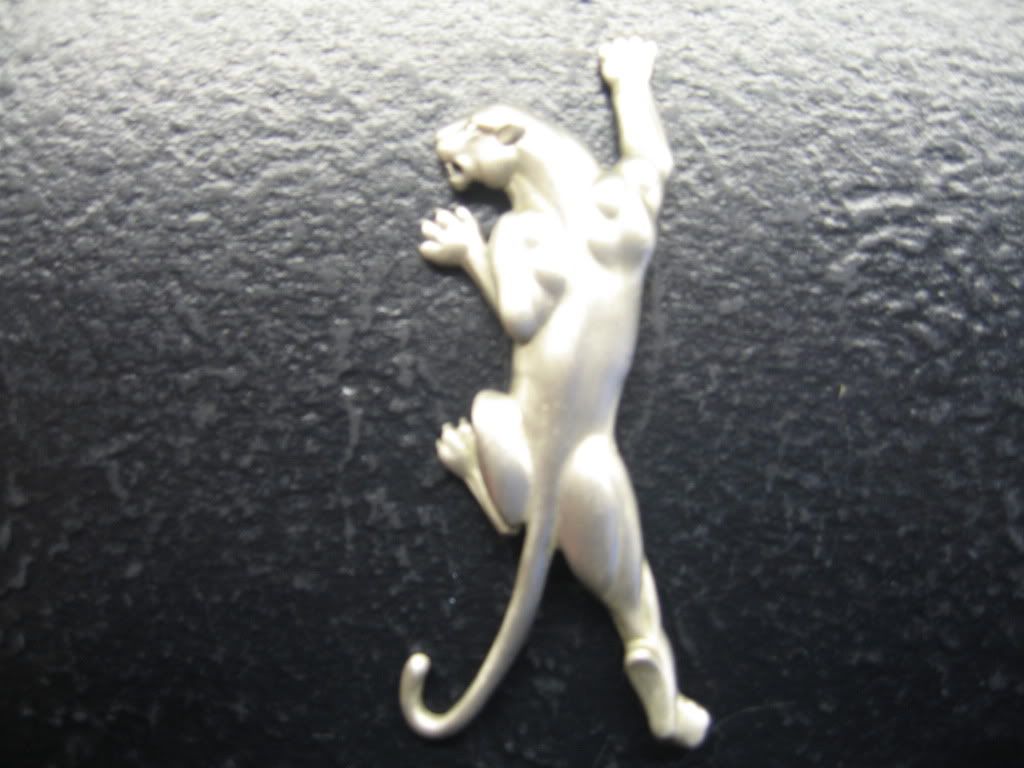
I also got a bit indulgent and bought a Panther sculpture to fit on the new grill when I fit it, cost a bit more than I was hoping but they do look good.

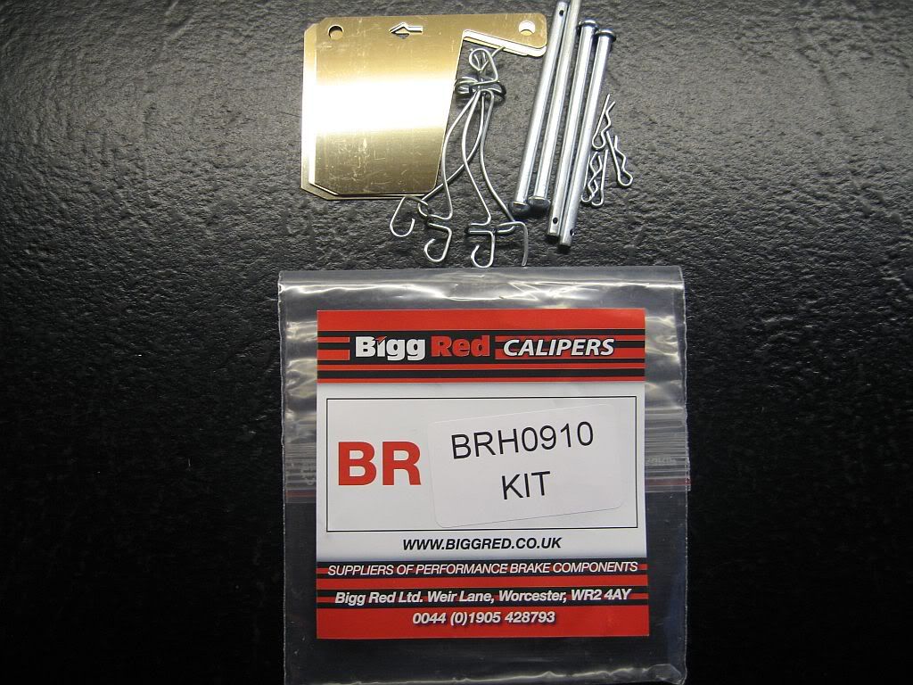
I was also wondering where to go to to buy new front brake caliper shims, pins and clips, well I finally found the Tech page on the Panther car club web site. I new there was one somewhere as I had read references to it but could never find it, then I finally looked in the Jump To drop down section and there at the bottom was the link to the Tech page. It is full of useful info including an article posted by Terry Borton on where to buy the shim kit and the number on ebay. So here it is for all.
Ebay # 310353988329
Shim kit
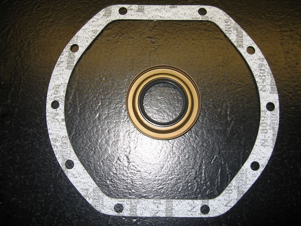
The rear axle is a modified Capri 2.8 Atlas which are still well catered for, so finding a Pinion oil seal and gasket for the diff was easy enough, I went for the upgraded seal and gasket on the premise that if its good enough for a rally car then its good enough for a Sunday driver like me. Just hope it fits.
Pinion seal Ebay address
Diff gasket Ebay address
Pinion oil seal & gasket
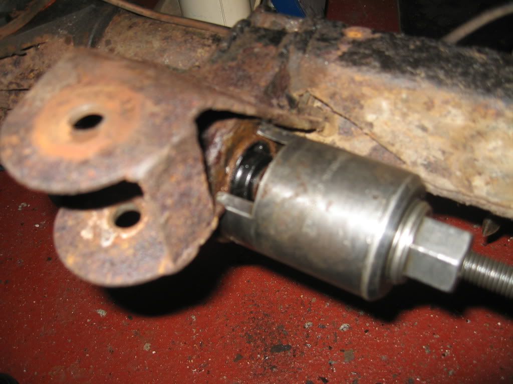
I also picked up an original Cortina void bush removal fitting tool for a fiver, very lucky as I have spent the afternoon removing the void bushes and it would have been a much harder job without it. When this job is done and anyone needs to borrow then just let me know.
Cortina void bush removal tool
I have been in contact with Terry about rear bushes for the Kallista and found that Deflex supplied a set of bushes for the car, unfortunately Deflex are no longer with us as they were bought up by Flo-flex. I have been in contact with Flo-flex and sent off a sample of the rear bushes, there are 3 different bushes fitted. The axle and upper arm are Cortina void bushes both slightly different, the Panhard rod and the lower arm bushes are of the bobbin type and are of the same size. I have posted the sample set today on next day delivery so hopefully i shall get a call soon saying they can supply, I hope so as the bobbin bushes get slightly distorted when removed as a lot of force is required so I doubt they will be able to be re-fitted. with this being a bit of a worry I have left the other ones in position until I get a ya or na. Which means my trip to the powder coaters is delayed.
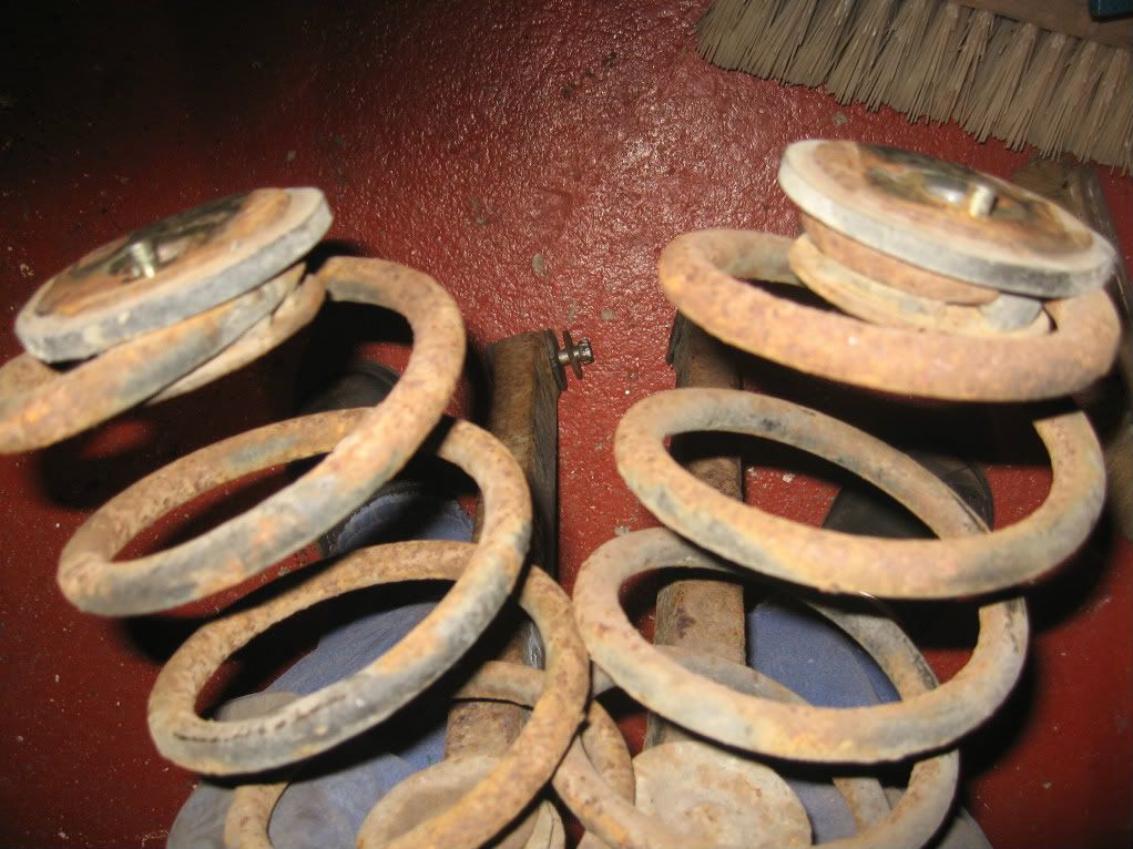
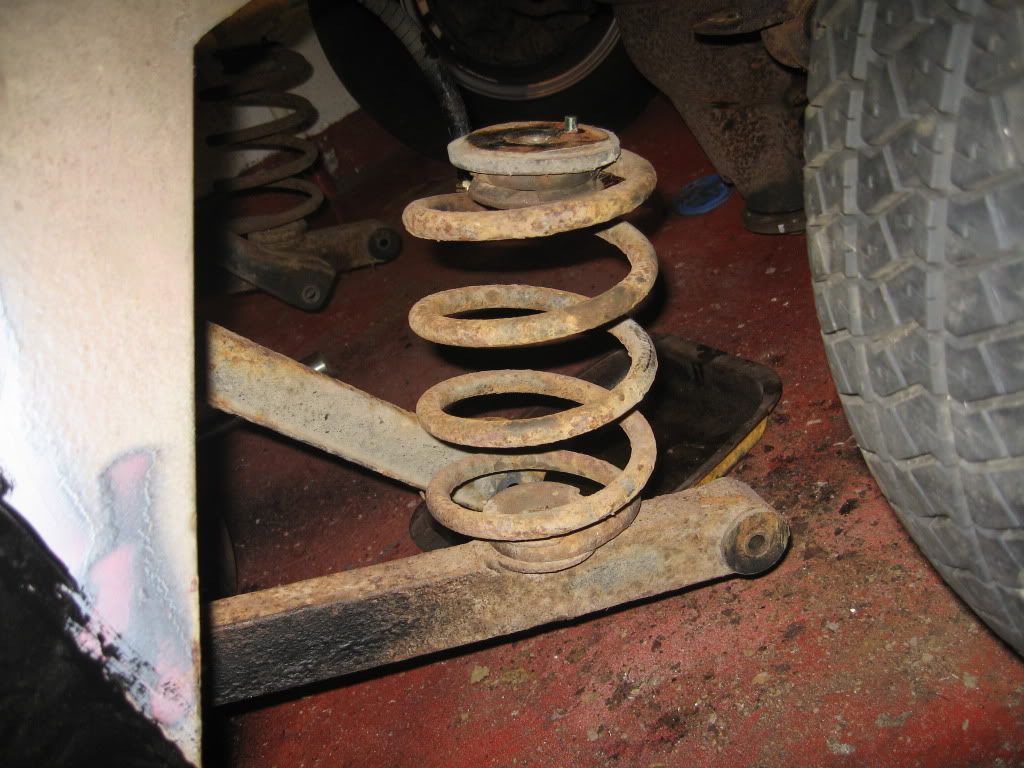
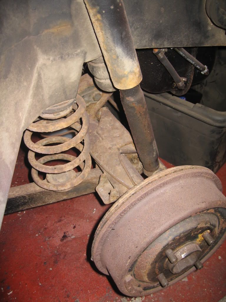
Another problem that I have found is that the top of the springs have a rubber interface fitted between the spring and chassis contact, this is riveted on, I could unfold the rivet and remove the rubber but it could cause damage. So I'm thinking of sandblasting and spraying these myself as I don't think they will like the powder coater's oven.
Rear springs
You can see the rubber on the top and under the top turn of the spring.
Not much done today, but will crack on tomorrow.
See ya Paul

Tuesday, 1 November 2011

Tuesday 01/11/2011

Hi
Well last day home today so been rather busy, all of the jobs that should have been done during the week have been handed down to me. Tried to escape but she had me, so after 2 cars washed all the floors vacuumed, washed and believe it or not; steam cleaned, add a few other bits and I was free.
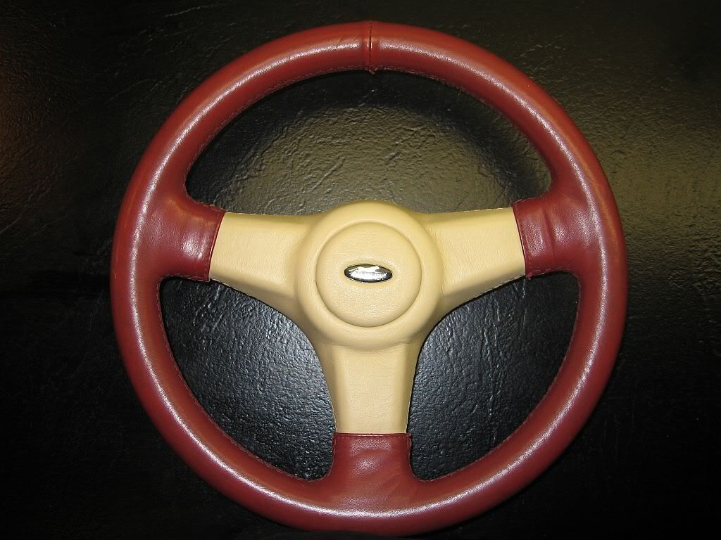
I did manage to get most of the jobs I had planned done but the highlight of the day was the arrival of the post man, he had the most fantastic steering wheel I have ever laid eye's, I've told Lynne that she is on the settee tonight and the steering wheel is getting her side of the bed.
My baby
Isn't she lovely! well some people are easily pleased. £108 + p+p and well worth it.

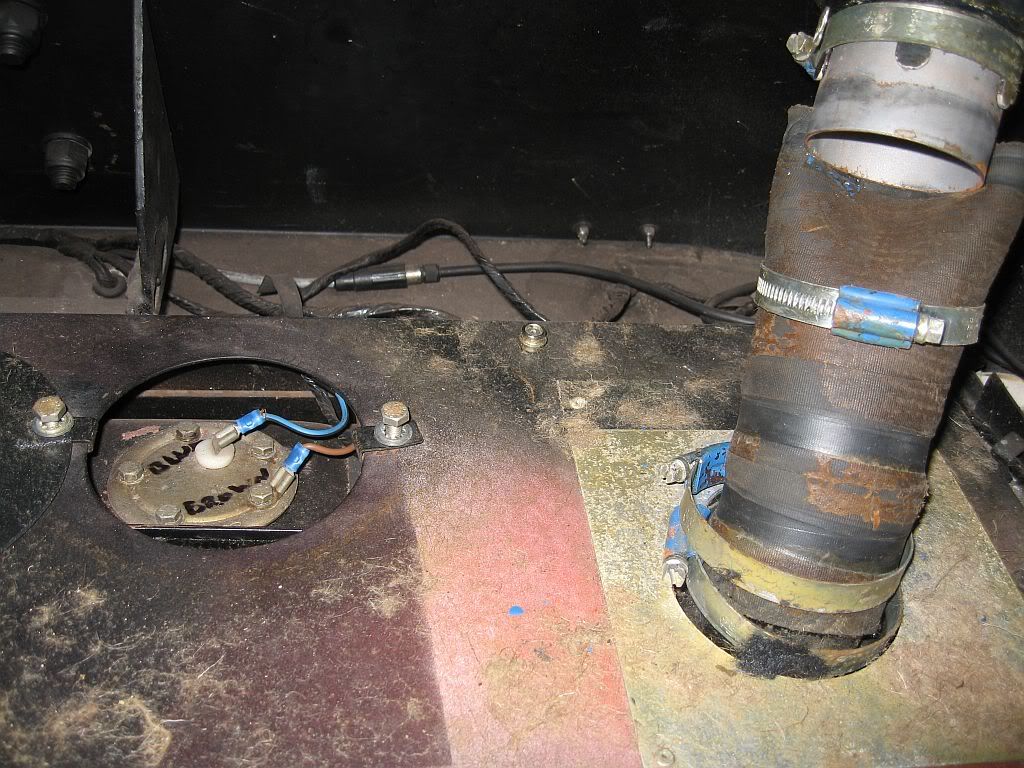
I started with the fuel tank, I had one of the brackets off yesterday so just one left before it could be removed, I new there was not much fuel in but the jack went under anyway. After a look in the back of the car I found the fuel filler pipe and the sender unit, and after disconnecting them all got the last bracket off
Filler and sender unit
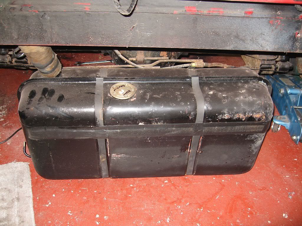
There are no bolts inside the car so it just lowered out nice and easy, I managed to empty around 4 litres out of the tank and this went into Lynne's car.
Fuel tank
I was a bit concerned considering the condition of the rest of the car as to the state of the tank, but I was surprised at how good a condition it is in. Not only the tank but the whole area above and around where it sits is very clean and in great condition, so all this needs is a good clean and spray paint.
The rest was not so easy as the tank, I first removed the hand brake mechanism which is just 2 R clips holding a pin and a bar that goes thru a bush attached to the diff, this was the easy bit
hand brake mech
The next step was to jack the weight of the axle but not lift it of the stands and then the first bit of the suspension system the Panhard rod. This was the start of the Battle of the Bolt, even my big air ratchet could not budge these, I even tried heating them but it eventually came down to the grinder which soon had them off, shame really as these are high tensile bolts which I will have to replace. The next battle came with the top 2 nuts on the dampers, no matter what I tried they would not budge so again the grinder took over.
After these 2 main items that hold everything up, it all was resting on the springs and the jack, I then removed the bolts from the prop shaft after paint marking the 2 flanges, I probably did not need to mark this but just to make sure; I shall chisel mark the paint marking before sand blasting. The rest of the nuts came of with the big gun and left them in place. The bolts I was most worried about was the top spring bolts but surprise surprise there practically threw themselves at me, it was strange though that the pass side had a 17mm head and the drivers had a 13mm head I found the same on some of the other bolts 19mm one side and 17mm the other. What's that about.
Spring un-bolted

Wheels on ready to drop
 I now fitted the wheels so there was less of a drop before I removed all of the other bolts, it was now just a matter of sliding off the prop shaft and levering the arms out from there brackets.
After releasing the jack out it rolled, I still had the brake pipe connected which I had difficulty getting at before so removed that and pulled out the axle.
You can see the oil stain that much clearer now on the diff, I don't know if its the pinion oil seal or just the cover gasket so I will have to change both just to make sure, well next time home.

I have received a number of emails from people after reading my blog and I would like to thank them for there help and advice, of course Terry is helping me continuously which is a great. John Manuel who let me know about the pit falls of changing seats even though they advertise as fitting the Kallista. This morning I received a very interesting one from Alun Williams concerning my thoughts of powder coating the drum brakes. Alun was an accident investigator for VOSA and has seen a number of incidents where the wheel nuts have become loose and the wheels coming off due to the powder coating softening because of the heat generated during braking. Again something that would never come to mind. 
I also received another email from Paul Yates, I had been in contact with Paul before concerning rocker covers. Paul has a website www.regaliarockercovers.co.uk and he makes rocker covers for specialist cars with the Essex engine, I contacted Paul thinking that the Essex had the same rocker design as the Cologne v6 and if he could make a set with Panther or Kallista imprinted in the top as he does with his others. Unfortunately this is not the case, but I am sure I am not the only one who would like a pair of alloy rocker covers, I have been looking on Ebay and they are quite a regular item and always go for around £130. SO if there are any like minded Kallisa owners reading this then contact Paul at his web site and maybe if enough people want a pair he will design a set for us.
Well that's all for this time home, back away for another 2 weeks.
see ya Paul

Monday, 31 October 2011

Monday 31/10/2011

Hi
Well the last bolt went into the subframe today and what a happy chappy I was.
First I had to go hunting for the new nuts and bolts, I also received an email from Terry concerning the positioning of these bolts and the importance of getting them in the correct way around. I never thought that this was an issue but as Terry explained the join area is a potential shear point as a number of owners have found out. You need to fit the bolts from the inside to the outside keeping the threads away from the scissor action 
Dome nut
The new bolts are stainless 12mm x 100mm 8.8 tensile strength and at Terry's suggestion I replaced the normal nut with a dome nut to give a nice clean finish. I was a bit worried about maintaining the tightness of the dome nuts so belt and braces I fitted a spring washer and also a good dab of thread lock, never coming off and at only £2.40 for both side I was well surprised
All that's left is to tighten the track rod ends and the tie rods but I shall leave this and do some basic tracking when the wheels are on so it will drive safely to the garage for its MOT and pro tracking.
I also fitted the other hub after a good strip and clean of the bearing, weather caps on and all done. 

So that's that now for the back end.

I have spent most of the day studying the rear underside and taking lots of photo's, I was going to push the car out to turn it around for easier access but a reworking of the work area in the garage has canceled this move.
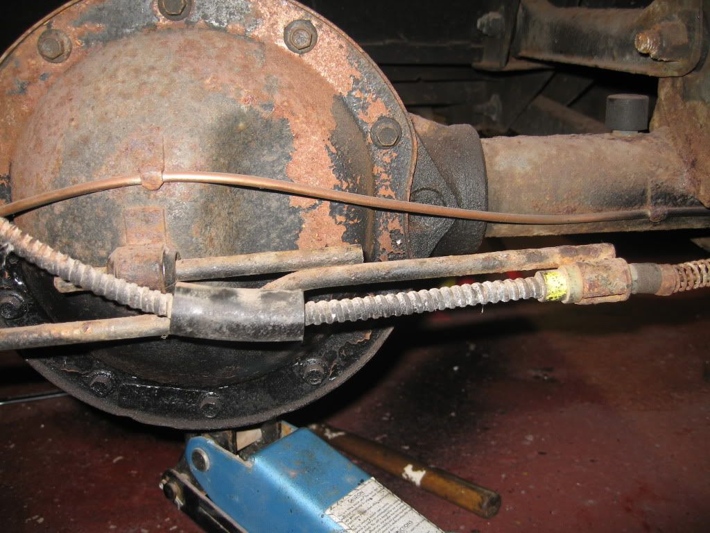
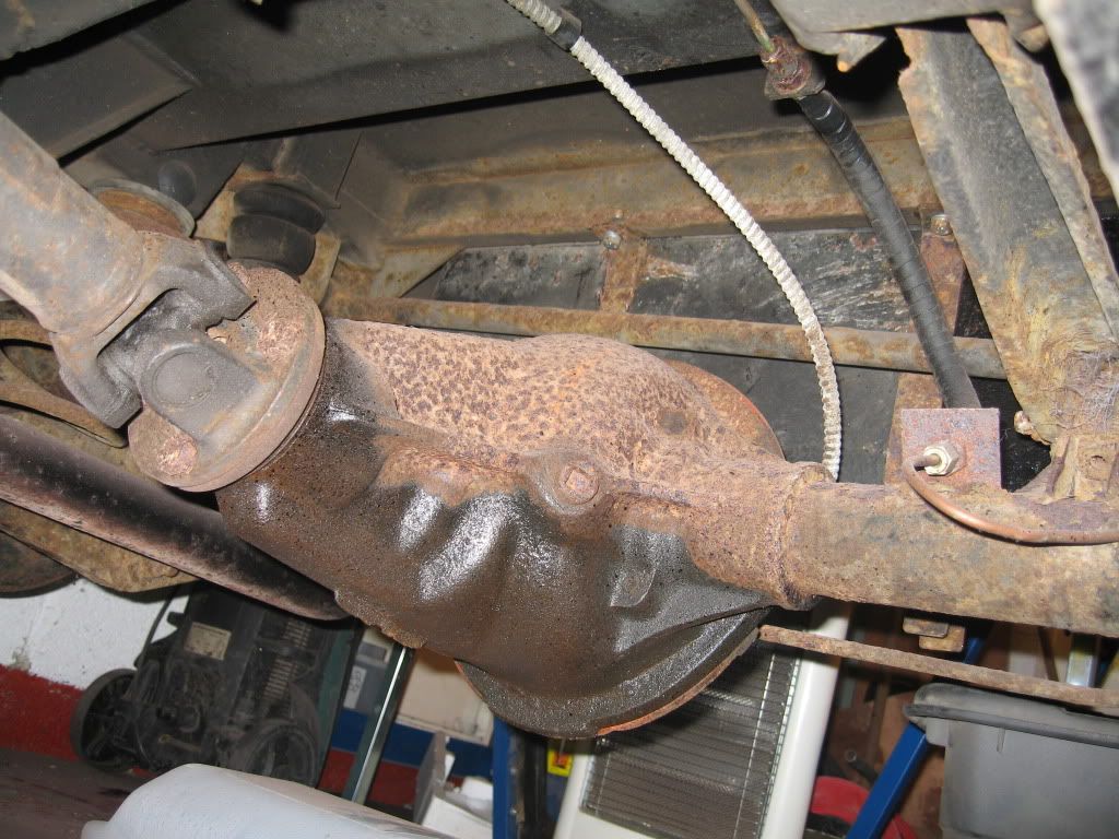
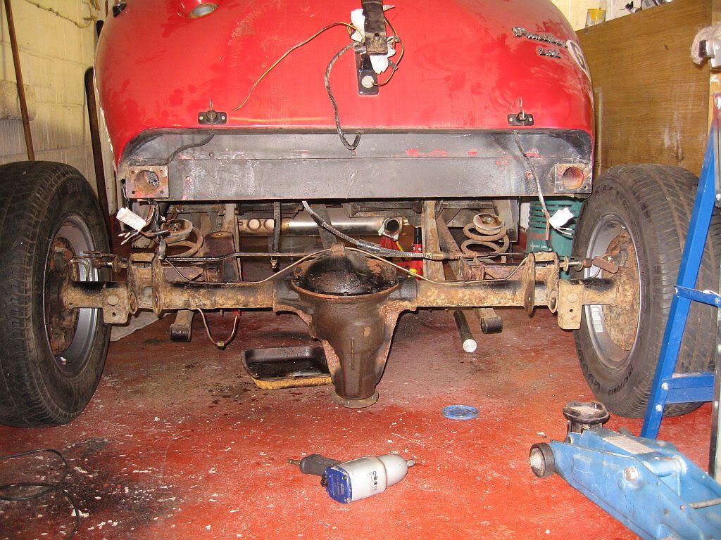
It seems that everything that contains oil in this car leaks, the diff being no different, it looks like the oil seal has gone. There is nothing on the garage floor but as you can see from the photo the oiling around the diff, hopefully it is just the cover gasket that is leaking.

Diff oil leak
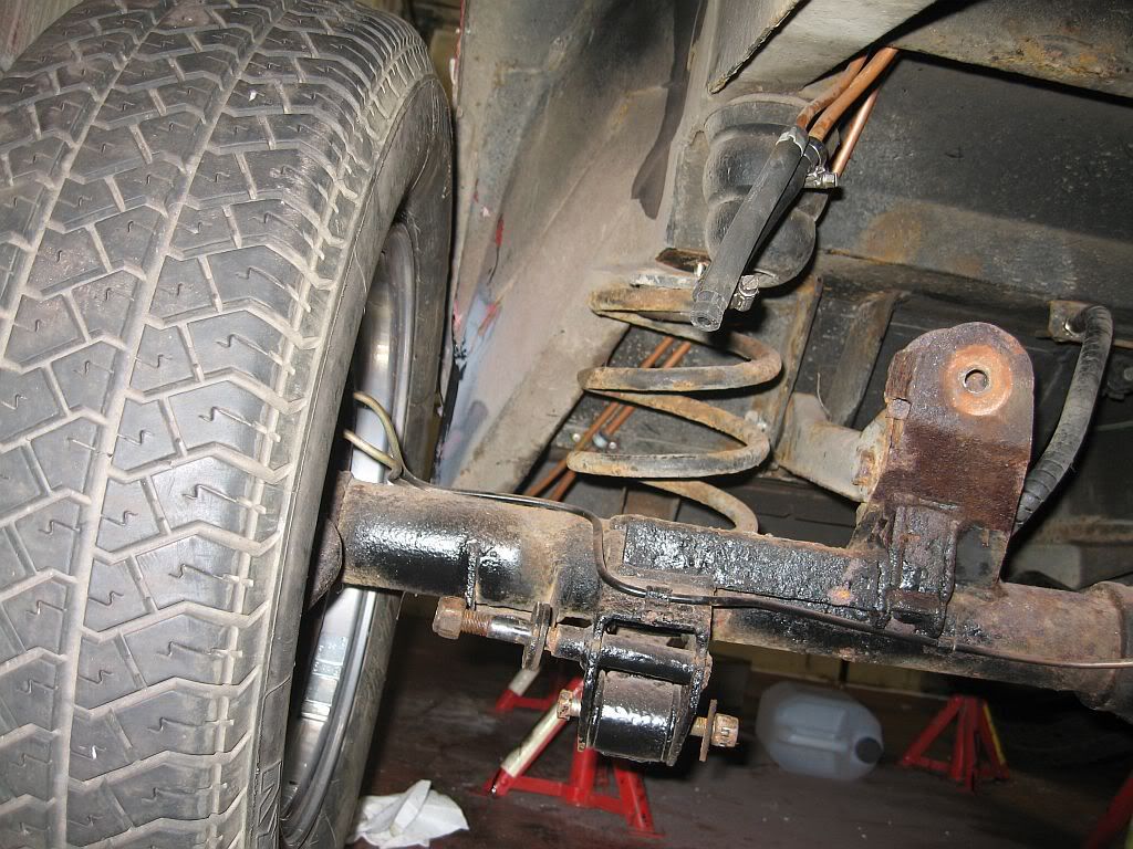
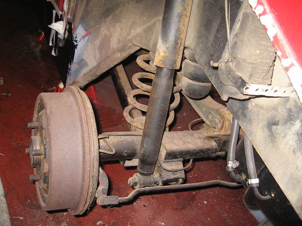
Anyone who has read this blog from the start and seen the state of the front suspension will not be at all surprised by the condition of the back end, but as with the front its only surface rust and underneath is good steel and will look like new with a good blast and powder coat.
Pass side rear suspension


 Well got to start somewhere:- so

First off is the rear exhaust pipe, this had a new U clamp on which came of easy, then I got wondering what the drums were like so off they came.
Drum brake
The inside of the drums looks good just the surface rust on the outside, I'll have these powder coated. The inside are a bit seized as you would expect after so long unused, I have over my numerous years owned around 15 cars yet I have never stripped down a drum brake, disc brakes yes but never drums. Looks a bit daunting but what the hell I'll give it a go. The bearing sound Ok but will check when I tear it apart.
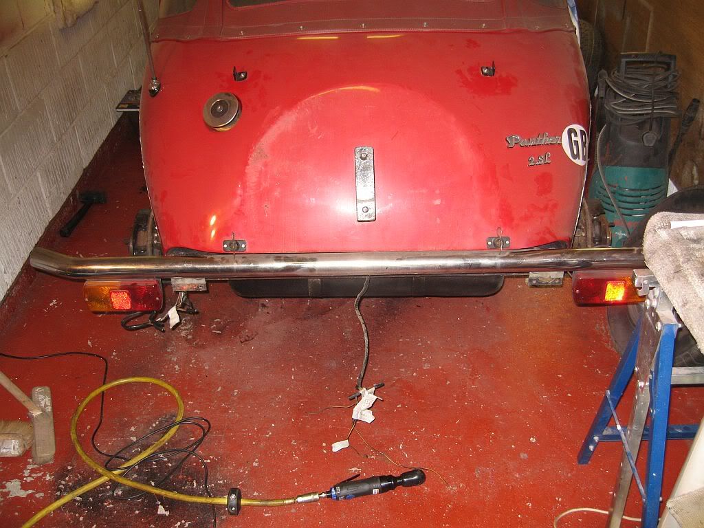
Next to come off was the spare wheel, luggage rack, number plate, lamp cluster and bumper. I have labeled all of the wiring as I removed it and found a bit of damage that will need sorting.

Sad back end

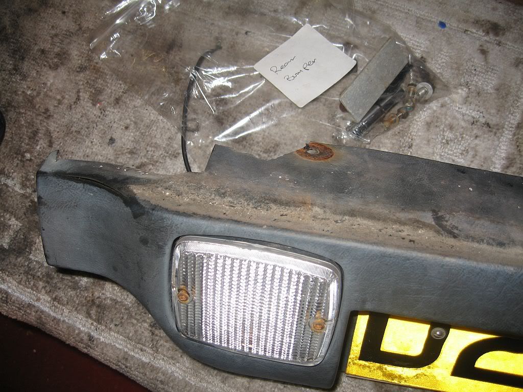
The damage is to the number plate / lamp cluster holder, this is just flimsy plastic, also all of the lamps will need replacing. I shall contact Bruno to see if he has a new one and lamps and also order new Spax dampers.


You can see the broken section by the rust stained area, if a new one is not available I shall repair and fiberglass the inside to give it more strength. The break had been looked at in the past as a newish piece of angle ally was bolted on to keep it in place. The number plate could do with replacing but as this one is the original Panther plate I shall give it a good clean and re-fit it.
Once the bumper was off I started looking at the fuel tank, part of the work done to the car before I bought it was the fuel system. All of the the pipe work from the tank to the fuel pump has been replaced also there are new stainless bolts in the tank brackets. The brackets need replacing so I shall make 2 new one's up  in stainless. I never finished removing the fuel tank, got to figure that one out so that's tomorrows job. 'O' yes and drop the whole rear axle suspension unit. Just a little job.
See ya Paul
Sunday, 30 October 2011

Wheel Bearings
Hi
Not much time to do things today but a bit of progress on the hubs, the roller bearings in the hubs (i have read) have a life of around 100,000 miles, so at 35,000 on the clock jut a clean, check, re-grease and re-fit.
The outer bearing is easy to remove and clean as it comes of with the removal of the hub, the inner roller is retained by the grease seal which has to be removed first. The book says to replace the seals after removal as they get damaged, I had no problem with the removal just a wide blade driver under the seal and it popped out, it was just a matter of cleaning out all the old grease and have a close inspection to ensure all is fine.
Hub bearing
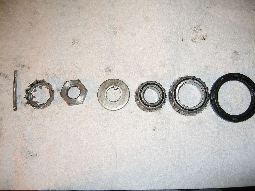
Here are all the bits laid out, right to left are:- Grease seal, inner roller, outer roller, tab washer, nut, nut cap and split pin. There are 2 more parts to the bearing that I have not removed and these are the other half's of the two rollers. These only need to be removed if replacing the bearing as they need to be knocked out with a drift and may get damaged.
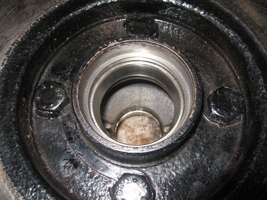
Hub inner bearing
You can see the 2 half's of the un-removed bearing in position on the cleaned hub.
I cleaned out as much of the old grease as I could and packed the inner race with new grease working it into the rollers as much as I could then slipped it in followed by the cleaned and checked grease seal. The hub is now fitted onto the stub shaft, the outer bearing is packed with grease and slid into position followed by the tab washer. 
Now comes the tightening, put the nut on and tighten by hand until the hub is positioned fully back, it is important that a little float is allowed in the hub to take into account of the expansion that will take place due to the friction heat created when driving. The Haynes manual says to tighten to 27 lb ft which is around 37Nm then to turn back 90 deg's to give the end float, unfortunately my torque wrench starts at around 50Nm so I had to use another method. Basically I just tightened with a shifter turning the hub constantly until the end float was lost then turned back 90 deg's. Give the hub a shake and the hub just moved around a mil which when on the road should take up to the correct tightness. I shall check again once the car has done a few miles.

Hub into position
I then fitted the nut cap and split pin, the cover is still wet from painting and shall fit tomorrow.
I have cleaned up the original disks, only a very small lip around the outer edge which I have ground off, sanded and cleaned the disc with brake cleaner and it looks in great condition.
There were 2 bearing manufactures used on the Cortina, Timken and Skefco, the bearings fitted on my 86 is Skefco.
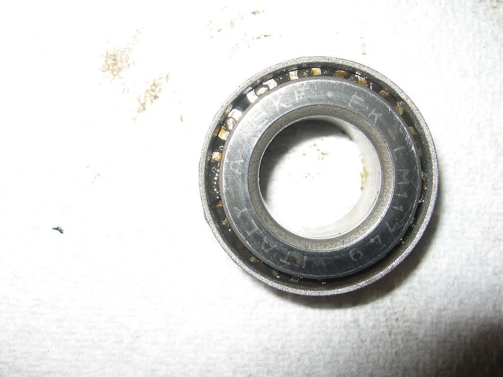
SKF bearing
This is the outer bearing with the bearing i.d stamped on  SKF EK-LM11749, I am sure that if anyone requires the Timkin order number Terry at the panther club will have it or know's who has it.
Just need to fit the other hub, find some new nuts & bolts for the subframe to chassis fit the wheels and I will be able to have a rolling car, tomorrow i think.
See ya Paul